
The multimeter is an indispensable tool for any electronics project, as it helps overcome countless challenges during project completion. This article will demonstrate how to create a cost-effective digital multimeter using an Arduino board and an OLED display. This multimeter is capable of measuring voltage, current, resistance, and capacitance. Upon completing the project, you will have your own multimeter at the lowest possible cost.
In simple words, a multimeter is a device that converts electrical parameters such as voltage, current and so on to a language we can understand. First prototypes of this widely used device (called galvanometer) were created in 1820. Despite being only capable of measuring current, they became an essential part of any electronics projects. Knowing how to use a multimeter is essential for any electronics project
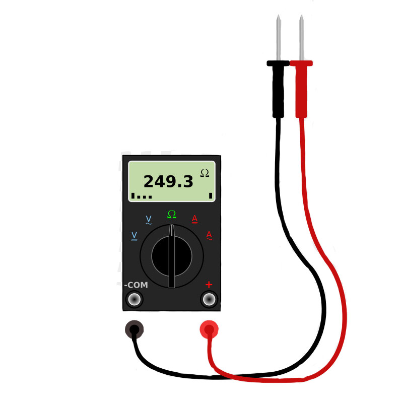
Multimeters are generally categorized as analog and digital. Analog multimeters use physical pointers to display values and are being used less and less. However, digital multimeters benefit from digital displays and are much more popular.
Multimeters measure various parameters. However, the most important ones are voltage, current and, resistance. Other parameters include capacitance, self-inductance, frequency, diode test, connectivity test, brightness, transistor test and, so on.
For this project, we will make a multimeter that can measure voltage, current, resistance and capacitance.
Various methods exist for measuring the voltage, such as using the hall effect, the simplest one is the voltage divider.
The voltage divider is a circuit that puts a fraction of the voltage between two resistors.
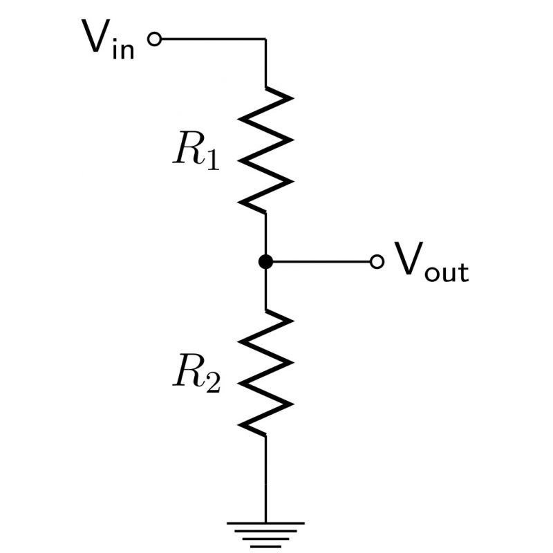
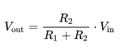
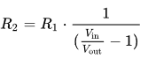
Now if we know the R1 and R2 resistance and the Vout values, we can easily calculate the voltage using the above formula.
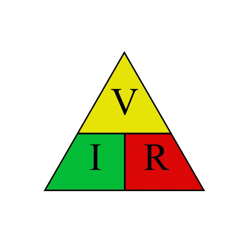
The simplest method for measuring the current is using Ohm’s law. This law states the electrical current in a path is directly proportional to the voltage divided by the resistance in that path.
Another technique for measuring the current is using the hall-effect principle. The passing of the electrical current creates a magnetic field and consequently the hall voltage. By measuring the hall voltage, you can calculate the magnetic field intensity and therefore the passing electrical current.
The same voltage divider technique can be used to measure the resistance. The only difference compared to measuring the voltage is that here, we know the input voltage, the resistance of R1 and the output voltage. R2 is the unknown variable.
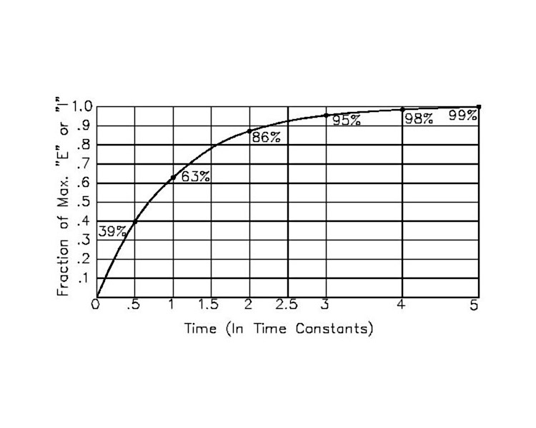
It takes a specific amount of time for the capacitor to charge to 63.2%. This is calculated using the following formula:
So if we know the resistance and the time it takes for the capacitor to charge to 63.2% of its capacitance, we can calculate the capacitance.
| Arduino UNO R3 | × | 1 |
| 0.96" I2C OLED Display Module | × | 1 |
| AC712 5A Current Sensor | × | 1 |
| Resistor 1k | × | 1 |
| Resistor 10k | × | 2 |
| Resistor 100k | × | 1 |
| Resistor 4.7k | × | 1 |
| Resistor 220 | × | 1 |
| Male to Female Jumper Wire | × | 1 |
| Micro Push Button Switch 5x6x6mm - 10 Pack | × | 1 |
| Arduino IDE |
We use the voltage divider technique for the voltmeter. We need the Arduino’s ADC unit to read the voltage.
Here we have used 10 and 4.7 kilo-ohm resistors for the voltage division circuit. Connect the wires according to the following diagram.
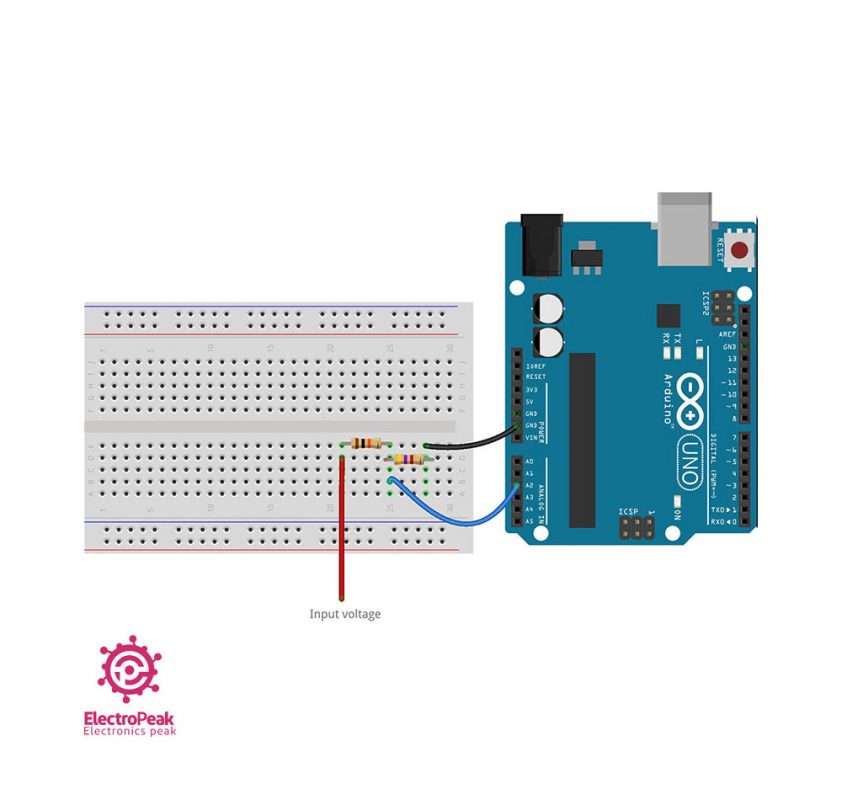
Since the input voltage for Arduino’s ADC is 5 volts, selecting these resistors will allow the measuring of voltages up to 15 volts. Higher voltages could damage your Arduino board.
By changing the resistors you can change the range of acceptable input voltages. The higher the input voltage, the lower the accuracy will be.
/* Voltmeter with Arduino modified on 21 Jul 2019 by Saeed Hosseini @ ElectropeakHome*/ const int VoltMeter = 2; float V = 0.00; void calculate_voltage() < float R1 = 10000.00; float R2 = 4700.00; float v_ref = 5.00; float resistor_ratio = 0.00; float adc_value = 0.00; float voltage = 0.00; resistor_ratio = (R2 / (R1 + R2)); for (int i = 0; i < 20 ; i++) < adc_value = adc_value + analogRead(VoltMeter); delay(3); >adc_value = adc_value / 20; voltage = ((adc_value * v_ref) / 1024); V = voltage / resistor_ratio; > void setup() < Serial.begin(9600); >void loop()
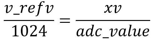
Here, using the formula for voltage division rule and reading voltage by the ADC unit, we calculate the input voltage.
To find the voltage using the ADC unit, we use the following proportion:
We use the AC712 sensor for making the ammeter. It is available as a module in various ranges. In this project, we are using the 5A range of this module.
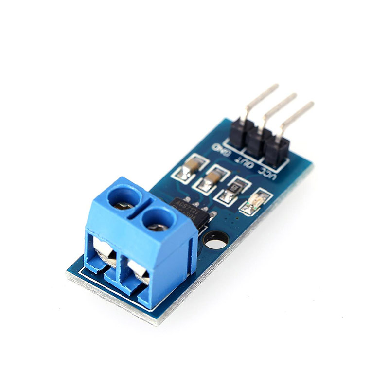
This sensor uses the hall effect to measure the current. Then it outputs a voltage proportional to the measured current, namely 185 millivolts for each amp of current.
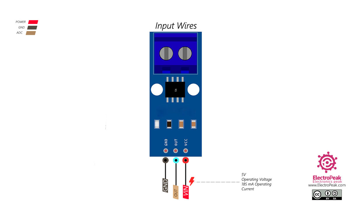
Connect the wires according to the following diagram.
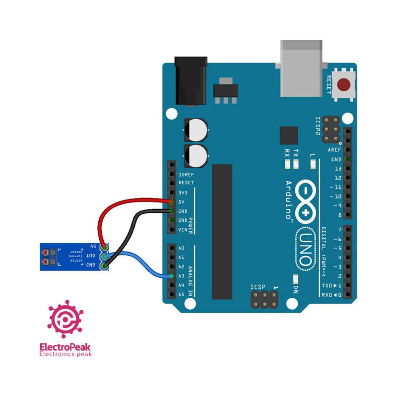
To measure the current, the ammeter has to be in series with the intended section to measure the current.
Upload the following code to your Arduino and view the results in the Serial Monitor window.
/* Ammeter with Arduino modified on 21 Jul 2019 by Saeed Hosseini @ Electropeak Home
*/ const int Ammeter = A2; float I = 0.00; void calculate_current() < int sensitivity = 185; int adc_value = 0; float v_ref = 4.94; float voltage = 0.00; float pure_voltage = 0.00; float offset_voltage = 2.47; for (int i = 0; i < 40 ; i++) < adc_value = adc_value + analogRead(Ammeter); delay(2); >adc_value = adc_value / 40; voltage = ((adc_value * v_ref) / 1024); pure_voltage = voltage - offset_voltage; // if(pure_voltage > 0.001) pure_voltage = 0.00; pure_voltage = pure_voltage * 1000; I = pure_voltage / sensitivity; Serial.println(String("ADC = ") + adc_value ); Serial.println(String("V = ") + voltage + "v"); Serial.println(String("Pure = ") + pure_voltage + "mv"); Serial.println(String("I = ") + I + "A"); > void setup() < Serial.begin(9600); >void loop() < calculate_current(); //Serial.println(String("I = ") + I + " mA"); delay(2000); >Here, the ADC unit reads the sensor’s output voltage, then calculates and displays the current using the mentioned proportion of 185 millivolts for each amp of current.
The first time you start the sensor, it should be free of any load and output voltage should be around 2.5 volts. Read this value carefully and substitute it for the offset-voltage variable preset.
We use the same voltage divider technique for making the ohmmeter.
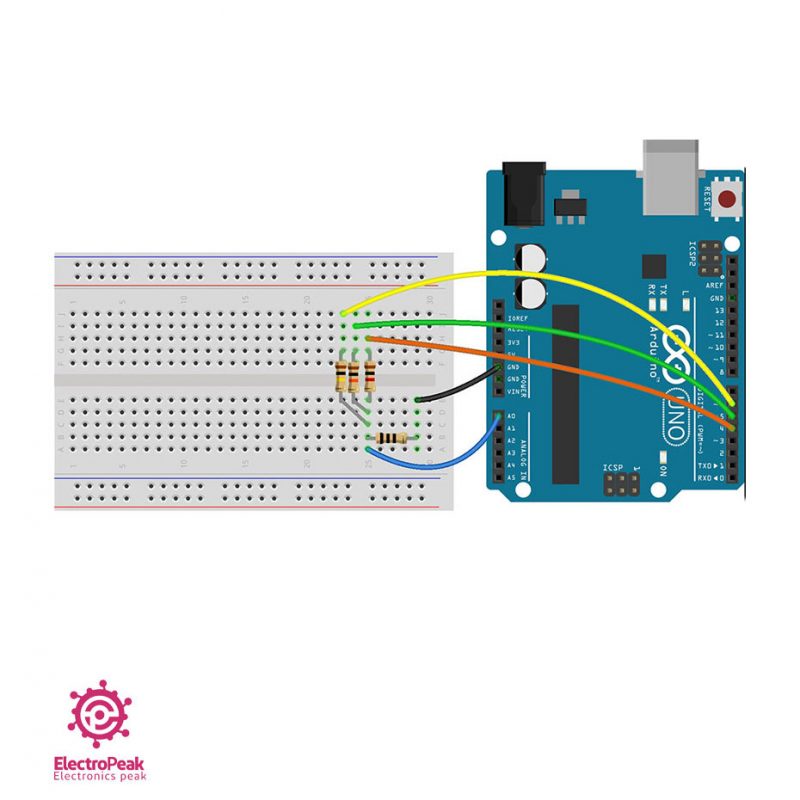
The range of resistors’ values is the main issue in an ohmmeter. The farther apart resistance values of the known and unknown resistors are, the less accurate results will become. So it would be better to use several resistors to maintain smaller ranges. You can manually change the resistors using a switch or set it up automatically.
In order to automatically change the resistance range, we measure the unknown resistor one by one using the known resistors. Using the known resistors and the measured values, we calculate more accurate values for the unknown resistors.
Here we have used three ranges of 1, 10 and 100 kilo-ohms. You can make changes based on your project requirements.
We have used the 1, 10 and 100 kilo-ohms resistors to set the ranges. Connect the wires according to the following diagram.
Upload the following code to your Arduino and view the results in the Serial Monitor window.
/* Ohmmeter with Arduino - Automatic range modified on 21 Jul 2019 by Saeed Hosseini @ ElectropeakHome*/ const int OhmMeter = 0; const int R3 = 6; const int R2 = 5; const int R1 = 4; float R = 0.00; void calculate_resistor() < float v_ref = 4.94; float r1 = 0.00; float r_ref1 = 1000.00; float adc_value1 = 0.00; float voltage1 = 0.00; float r2 = 0.00; float r_ref2 = 10000.00; float adc_value2 = 0.00; float voltage2 = 0.00; float r3 = 0.00; float r_ref3 = 100000.00; float adc_value3 = 0.00; float voltage3 = 0.00; pinMode(R1, OUTPUT); pinMode(R2, INPUT); pinMode(R3, INPUT); digitalWrite(R1, HIGH); for (int i = 0; i < 20 ; i++) < adc_value1 = adc_value1 + analogRead(OhmMeter); delay(3); >adc_value1 = adc_value1 / 20; if (adc_value1 < 1022.90) < voltage1 = ((adc_value1 * v_ref) / 1024); r1 = (voltage1 * r_ref1) / (v_ref - voltage1); >pinMode(R1, INPUT); pinMode(R2, OUTPUT); pinMode(R3, INPUT); digitalWrite(R2, HIGH); for (int i = 0; i < 20 ; i++) < adc_value2 = adc_value2 + analogRead(OhmMeter); delay(3); >adc_value2 = adc_value2 / 20; if (adc_value2 < 1022.90) < voltage2 = ((adc_value2 * v_ref) / 1024); r2 = (voltage2 * r_ref2) / (v_ref - voltage2); >pinMode(R1, INPUT); pinMode(R2, INPUT); pinMode(R3, OUTPUT); digitalWrite(R3, HIGH); for (int i = 0; i < 20 ; i++) < adc_value3 = adc_value3 + analogRead(OhmMeter); delay(3); >adc_value3 = adc_value3 / 20; if (adc_value3 < 1022.90) < voltage3 = ((adc_value3 * v_ref) / 1024); r3 = (voltage3 * r_ref3) / (v_ref - voltage2); >r1 = r1 / 1000; r2 = r2 / 1000; r3 = r3 / 1000; if (r1 < 2 && r2 < 101 && r3 < 1001) R = r1*1000; else if (r1 >2 && r2 < 101 && r3 < 1001) R = r2; else if (r1 >2 && r2 > 101 && r3 < 2000) R = r3; else R = 0.00; Serial.print("R = "); Serial.println(R, 2); >void setup() < Serial.begin(9600); >void loop()
In this piece of code, unknown resistance values are calculated one by one, using the known resistors. Then we use the conditions to calculate the main resistor’s resistance.
In order to measure the resistance accurately and turn Arduino pins on and off, setting them as LOW wouldn’t suffice. Arduino pins should be defined as inputs so they can be fully turned off.
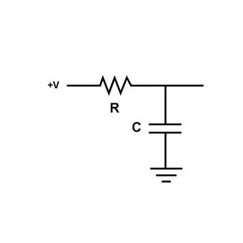
We are using the same capacitor’s charging time algorithm to measure the capacitance. After the measurement process, the capacitor should be discharged for the next measurement.
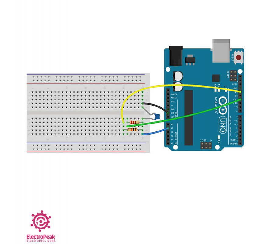
Here we used a 10 kilo-ohm resistor to charge the capacitor and a 220-ohm resistor for discharge.
Connect the wires according to the following diagram.
Upload the following code to your Arduino and view the results in the Serial Monitor window.
/* Capacitance meter with Arduino modified on 21 Jul 2019 by Saeed Hosseini @ Electropeak base on: https://www.arduino.cc/en/Tutorial/CapacitanceMeterHome*/ const int CapacitancMeter = 1; const int ChargePin = 13; const int DischargePin = 11; float C = 0.00; void calculate_capacitance() < unsigned long start_time; unsigned long elapsed_time; float microFarads; float nanoFarads; float r_ref = 10000.00; digitalWrite(ChargePin, HIGH); start_time = millis(); while (analogRead(CapacitancMeter) < 648) <>elapsed_time = millis() - start_time; microFarads = ((float)elapsed_time / r_ref) * 1000; if (microFarads > 1) < C = microFarads; >else < nanoFarads = microFarads * 1000.0; C = nanoFarads; >digitalWrite(ChargePin, LOW); pinMode(DischargePin, OUTPUT); digitalWrite(DischargePin, LOW); while (analogRead(CapacitancMeter) > 0) <> pinMode(DischargePin, INPUT); > void setup() < Serial.begin(9600); pinMode(ChargePin, OUTPUT); digitalWrite(ChargePin, LOW); >void loop()
The measurement algorithm is as follows:
If you increase the known resistor’s resistance, the charging time will increase, resulting in more accurate results. However, longer charge duration reduces the measurable capacitance range. If you decrease the resistance, charge time will be reduced and the measurable range increases, at the cost of losing accuracy.
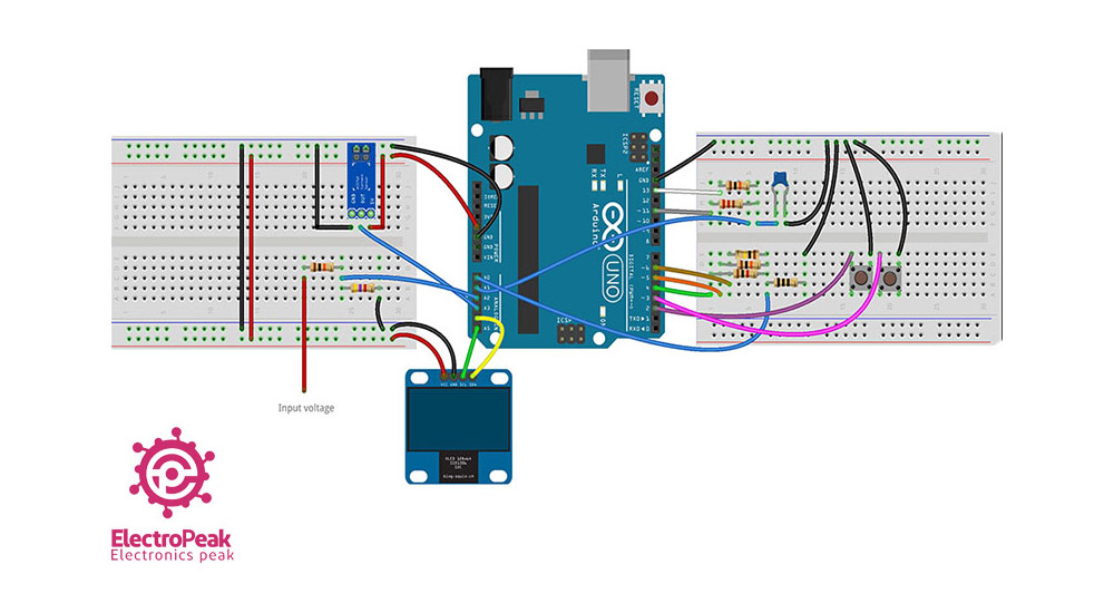
Now that all target parameters are measured, you can complete your multimeter by adding an OLED display and two buttons to navigate the menus.
Upload the following code to your Arduino and view the results in the Serial Monitor window.
/* Digital Multimeter with Arduino and OLED modified on 21 Jul 2019 by Saeed Hosseini @ Electropeak Home
*/ #include #include #include #include "logo.h" #define SCREEN_WIDTH 128 #define SCREEN_HEIGHT 32 #define OLED_RESET -1 Adafruit_SSD1306 display(SCREEN_WIDTH, SCREEN_HEIGHT, &Wire, OLED_RESET); const int select_button = 2; const int right_button = 3; const int OhmMeter = A0; const int CapacitancMeter = A1; const int VoltMeter = A2; const int Ammeter = A3; const int R3 = 6; const int R2 = 5; const int R1 = 4; const int ChargePin = 13; const int DischargePin = 11; boolean is_select = false; int navigator = 0; int flag = 0; float R = 0.00; float V = 0.00; float I = 0.00; float C = 0.00; boolean nano = false; boolean kilo = false; boolean mili = false; void OLED_init() < if (!display.begin(SSD1306_SWITCHCAPVCC, 0x3C)) < Serial.println(F("SSD1306 allocation failed")); for (;;); >display.clearDisplay(); diplay_logo(15, 3, Electropeak, F_LOGO_WIDTH, F_LOGO_HEIGHT); display.display(); delay(2000); display_clear(); > void display_clear() < display.clearDisplay(); display.display(); >void diplay_logo(int x, int y, const uint8_t *bitmap, int w, int h) < display.drawBitmap(x, y, bitmap, w, h, WHITE); >void display_text(int sz, int x, int y, String str) < display.setTextSize(sz); display.setTextColor(WHITE); display.setCursor(x, y); display.println(str); >void display_number(int sz, int x, int y, double num) < display.setTextSize(sz); display.setTextColor(WHITE); display.setCursor(x, y); display.println(num); >void calculate_resistor() < float v_ref = 4.94; float r1 = 0.00; float r_ref1 = 1000.00; float adc_value1 = 0.00; float voltage1 = 0.00; float r2 = 0.00; float r_ref2 = 10000.00; float adc_value2 = 0.00; float voltage2 = 0.00; float r3 = 0.00; float r_ref3 = 100000.00; float adc_value3 = 0.00; float voltage3 = 0.00; pinMode(R1, OUTPUT); pinMode(R2, INPUT); pinMode(R3, INPUT); digitalWrite(R1, HIGH); for (int i = 0; i < 20 ; i++) < adc_value1 = adc_value1 + analogRead(OhmMeter); delay(3); >adc_value1 = adc_value1 / 20; if (adc_value1 < 1022.90) < voltage1 = ((adc_value1 * v_ref) / 1024); r1 = (voltage1 * r_ref1) / (v_ref - voltage1); >pinMode(R1, INPUT); pinMode(R2, OUTPUT); pinMode(R3, INPUT); digitalWrite(R2, HIGH); for (int i = 0; i < 20 ; i++) < adc_value2 = adc_value2 + analogRead(OhmMeter); delay(3); >adc_value2 = adc_value2 / 20; if (adc_value2 < 1022.90) < voltage2 = ((adc_value2 * v_ref) / 1024); r2 = (voltage2 * r_ref2) / (v_ref - voltage2); >pinMode(R1, INPUT); pinMode(R2, INPUT); pinMode(R3, OUTPUT); digitalWrite(R3, HIGH); for (int i = 0; i < 20 ; i++) < adc_value3 = adc_value3 + analogRead(OhmMeter); delay(3); >adc_value3 = adc_value3 / 20; if (adc_value3 < 1022.90) < voltage3 = ((adc_value3 * v_ref) / 1024); r3 = (voltage3 * r_ref3) / (v_ref - voltage2); >r1 = r1 / 1000; r2 = r2 / 1000; r3 = r3 / 1000; if (r1 < 2 && r2 < 101 && r3 < 1001) R = r1 * 1000; else if (r1 >2 && r2 < 101 && r3 < 1001) R = r2; else if (r1 >2 && r2 > 101 && r3 < 2000) R = r3; else R = 0.00; if (R < 1) < R = R * 1000; kilo = false; >else < kilo = true; >> void calculate_capacitance() < unsigned long start_time; unsigned long elapsed_time; float microFarads; float nanoFarads; float r_ref = 10000.00; digitalWrite(ChargePin, HIGH); start_time = millis(); while (analogRead(CapacitancMeter) < 648) <>elapsed_time = millis() - start_time; microFarads = ((float)elapsed_time / r_ref) * 1000; if (microFarads > 1) < C = microFarads; nano = false; >else < nanoFarads = microFarads * 1000.0; C = nanoFarads; nano = true; >digitalWrite(ChargePin, LOW); pinMode(DischargePin, OUTPUT); digitalWrite(DischargePin, LOW); while (analogRead(CapacitancMeter) > 0) <> pinMode(DischargePin, INPUT); > void calculate_voltage() < float R1 = 10000.00; float R2 = 4700.00; float v_ref = 5.00; float resistor_ratio = 0.00; float adc_value = 0.00; float voltage = 0.00; resistor_ratio = (R2 / (R1 + R2)); for (int i = 0; i < 20 ; i++) < adc_value = adc_value + analogRead(VoltMeter); delay(3); >adc_value = adc_value / 20; voltage = ((adc_value * v_ref) / 1024); V = voltage / resistor_ratio; > void calculate_current() < int sensitivity = 185; int adc_value = 0; float v_ref = 4.94; float voltage = 0.00; float pure_voltage = 0.00; float offset_voltage = 2.47; for (int i = 0; i < 40 ; i++) < adc_value = adc_value + analogRead(Ammeter); delay(2); >adc_value = adc_value / 40; voltage = ((adc_value * v_ref) / 1024); pure_voltage = voltage - offset_voltage; pure_voltage = pure_voltage * 1000; I = pure_voltage / sensitivity; if (I < 1) < I = I * 1000; mili = true; >else < mili = false; >> void setup() < Serial.begin(9600); OLED_init(); pinMode(right_button, INPUT_PULLUP); pinMode(select_button, INPUT_PULLUP); pinMode(ChargePin, OUTPUT); digitalWrite(ChargePin, LOW); >void loop() < if (digitalRead(right_button) == 0) < navigator++; while (digitalRead(right_button) == 0); delay(5); if (navigator >3) navigator = 0; Serial.println(navigator); > if ( digitalRead(select_button) == 0) < is_select = true; while ( digitalRead(select_button) == 0); >if (navigator == 0) < display.clearDisplay(); diplay_logo(0, 0, RightArrow, F_LOGO_WIDTH, F_LOGO_HEIGHT); display_text(2, 17, 8, "Resistor"); display.display(); while (is_select) < display.clearDisplay(); display_text(1, 0, 0, "Resistor"); display_text(2, 12, 8, "R="); display_number(2, 42, 8, R); if (kilo) display_text(1, 115, 15, "k"); display.display(); calculate_resistor(); if ( digitalRead(select_button) == 0) < is_select = false; while ( digitalRead(select_button) == 0); >> > if (navigator == 1) < display.clearDisplay(); diplay_logo(0, 0, BothArrow, F_LOGO_WIDTH, F_LOGO_HEIGHT); display_text(2, 17, 8, "Voltage"); display.display(); while (is_select) < display.clearDisplay(); display_text(1, 0, 0, "Voltage"); display_text(2, 12, 8, "V="); display_number(2, 42, 8, V); display_text(1, 115, 15, "v"); display.display(); calculate_voltage(); if ( digitalRead(select_button) == 0) < is_select = false; while ( digitalRead(select_button) == 0); >> > if (navigator == 2) < display.clearDisplay(); diplay_logo(0, 0, BothArrow, F_LOGO_WIDTH, F_LOGO_HEIGHT); display_text(2, 17, 8, "Current"); display.display(); while (is_select) < display.clearDisplay(); display_text(1, 0, 0, "Current"); display_text(2, 12, 8, "I="); display_number(2, 42, 8, I); if (mili) display_text(1, 115, 15, "mA"); if (!mili) display_text(1, 115, 15, "A"); display.display(); calculate_current(); if ( digitalRead(select_button) == 0) < is_select = false; while ( digitalRead(select_button) == 0); >> > if (navigator == 3) < display.clearDisplay(); diplay_logo(0, 0, LeftArrow, F_LOGO_WIDTH, F_LOGO_HEIGHT); display_text(2, 12, 8, "Capacitor"); display.display(); while (is_select) < display.clearDisplay(); display_text(1, 0, 0, "Capacitor"); display_text(2, 12, 8, "C="); display_number(2, 42, 8, C); if (nano) display_text(1, 115, 22, "nF"); if (!nano) display_text(1, 115, 22, "uF"); display.display(); calculate_capacitance(); if ( digitalRead(select_button) == 0) < is_select = false; while ( digitalRead(select_button) == 0); >> > >